Pass the CoC in South Africa: Earthing for solar inverters
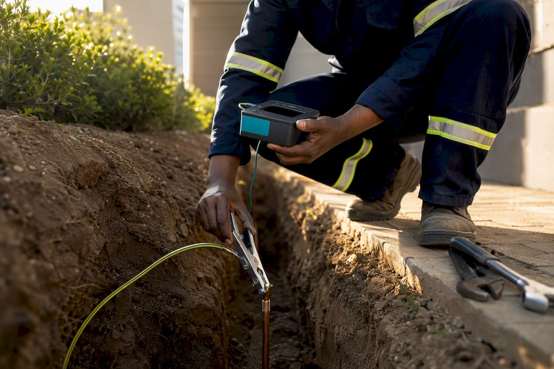
Every solar inverter installation needs its metal components bonded to earth for safety, full stop. What's optional is whether a DC conductor gets intentionally grounded, and that hinges entirely on inverter topology. Transformerless inverters typically use isolation monitoring instead of a DC ground, while transformer-isolated units may need one. Check the manufacturer's wiring diagram and let a registered electrician verify everything before the Certificate of Compliance gets signed.
*TL;DR:>
- Transformerless inverters typically rely on isolation monitoring and should not have a DC ground bonded to avoid fault trips, unlike transformer-isolated units that may require bonding.*
- All exposed metal components, including module frames, mounting rails, inverter chassis, and cable trays, must be bonded with listed hardware and tested for continuity and proper connection.
- Proper sizing and selection of earth conductors depend on specific OCPD ratings, with copper used for GECs and a target earth resistance below 5 ohms for residences, closer to 1 ohm for commercial systems.
- A poorly bonded or corroded earthing system can cause shock, fire hazards, and inspection failures, making regular testing and maintenance essential for safety and compliance.
- Verified installer credentials, thorough wiring and continuity tests, and thorough documentation are crucial to prevent costly rework, warranty issues, and insurance claims related to earthing errors.
Table of Contents
- Earthing for solar inverter systems: protective vs functional grounding
- How inverter topology decides your grounding approach
- What actually needs to be bonded on a PV array
- Designing an earthing system that actually holds up
- Why surge protection is only as good as your earthing
- The mistakes that fail inspections, and how to avoid them
- Keeping earth connections solid for the long haul
- Testing and commissioning: the numbers inspectors actually check
- Regulatory compliance: what SANS 10142-1 actually requires
- Impact of soil resistivity and different soil types on earthing system design
- Safety considerations and risk mitigation for improper earthing
- How moisture, temperature, and corrosion affect earthing over time
- How Solarza connects you with installers who get earthing right
- Get matched with a compliant installer through Solarza
- Standards and guides worth keeping on hand
- Sources
- FAQ
Earthing for solar inverter systems: protective vs functional grounding
The confusion around earthing for solar inverter installations almost always traces back to one thing: people use "grounding" to mean two different jobs. Protective earthing, handled by the equipment grounding conductor (EGC), gives fault current a safe path back to source and bonds every exposed metal surface so nobody gets shocked touching a rail or an inverter case. This is never optional. It applies to every grid-tied or hybrid system regardless of brand or size, and it's exactly what a registered electrician checks before signing a CoC under SANS 10142-1.
Functional or system grounding is a different animal. It refers to deliberately referencing one DC conductor to earth, something certain inverter designs use as part of their internal fault-protection scheme.
- Equipment grounding conductor (EGC): bonds chassis, frames, and enclosures. Mandatory, always.
- Grounding electrode conductor (GEC): connects the whole bonded system to an earth electrode, giving it a real-world earth reference.
- Functional/system grounding: intentionally earthing a DC pole, used by some inverter topologies and never assumed by default.
Mixing these up is where installers get into trouble, particularly with modern transformerless hardware.
How inverter topology decides your grounding approach
Whether you bond a DC pole to earth comes down almost entirely to whether your inverter is transformerless or transformer-isolated, and getting this wrong can shut the whole system down.
Transformerless (TL) inverters keep the DC array electrically floating and lean on internal isolation monitoring to detect insulation faults instead of a hard DC bond. Add a DC ground to one of these units and you risk creating a permanent fault path, which typically trips the inverter or throws it into a persistent error state until the bond is removed, since bonding a DC conductor on a transformerless inverter can create faults that isolation monitoring alone can't clear. Transformer-isolated inverters are built differently. Galvanic isolation between DC and AC sides means some of these units call for a bonded DC pole and a distinct ground-fault-protection arrangement, so the same rule doesn't apply across both types.
- Pull the spec sheet and confirm topology before touching any bonding jumper.
- Locate the FE (functional earth) and PE (protective earth) terminals and don't confuse them.
- Use a two-pole DC disconnect on transformerless systems, since correct OCPD and disconnect arrangements differ by inverter type.
- Record the exact inverter model and firmware version in the commissioning paperwork.
Pro Tip: If you can't find a clear statement on DC grounding in the manual, call the manufacturer's technical line before commissioning. Guessing on this one voids warranties fast.
For a broader look at what's on the market and how models differ, Solarza's inverter comparison guide is a reasonable starting point before you commit to a spec.
What actually needs to be bonded on a PV array
A rooftop array has more exposed metal than most homeowners realize, and every piece of it needs a verified path to earth.
- Module frames — each frame bonded individually, not assumed continuous through the rail.
- Mounting rails — continuity tested end to end, especially across splices.
- Inverter chassis — bonded via the manufacturer's dedicated PE terminal.
- Cable trays and metal conduit — bonded at both ends of any run.
- AC distribution board earth point — the final tie-in to the building's main earth.
Use listed bonding hardware, WEEB-style lugs or equivalent UL or IEC listed clamps, continuous copper conductors, and bolted connections you've physically verified with a meter. Anodised aluminium looks conductive and often isn't; never trust it as your only bonding path. Where rails use plastic joiners or non-conductive fasteners, run a dedicated bonding jumper across that joint. Skipping this step is one of the most common reasons rail sections fail continuity testing.
Designing an earthing system that actually holds up
Two conductors do the real work in any earthing system, and installers who blur the distinction between them tend to size things wrong. The EGC carries fault current back to source during a fault. The GEC connects the bonded system to the earth electrode, giving the whole installation a stable reference point relative to the ground itself. Both matter, but they're not interchangeable, and code treats them differently for a reason.
Sizing isn't guesswork. Conductor size is derived from the overcurrent protective device (OCPD) rating upstream, and SANS 10142-1 sets out the tables a registered electrician uses to make that call correctly for the installation's specific circuit protection. A few material rules apply regardless of system size:
- Never use aluminium for a buried grounding electrode conductor. Corrosion at the electrode connection defeats the whole point of the electrode.
- Use irreversible compression fittings or exothermic welds for any GEC splice, especially underground ones. Mechanical clamps degrade over time in buried conditions.
- Bond every auxiliary earth rod into the main earthing system rather than leaving it as a standalone electrode, since an unbonded rod can create a potential difference that's arguably worse than having no auxiliary rod at all.
Target earth resistance: Industry guidance suggests keeping earth resistance below 5 ohms for most residential PV installations, with commercial sites often targeting closer to 1 ohm. Lower resistance isn't just a compliance nicety. It directly improves how effectively your surge protection devices can do their job, which brings us to the next piece of the puzzle.
Soil conditions, electrode depth, and how many rods you drive all affect whether you hit that number on the first test, something worth planning for before you're standing in a trench with a resistance meter reading higher than you'd like.
Why surge protection is only as good as your earthing
A surge protection device (SPD) is only as effective as the earth path behind it. Correct SANS 10142-1-compliant earthing and bonding are required for SPDs to actually work, because a poorly earthed SPD provides little or no real protection even if it's correctly wired and rated. It divert surge energy to earth, and if that earth path has high impedance, the energy has nowhere useful to go.
Placement matters as much as the device itself:
- Fit an SPD at the DC combiner or string input, rated for the array's maximum voltage.
- Install a Type 2 SPD on the AC side, typically at the inverter output or the main distribution board.
- Add a third unit at the main DB if the service entrance is a meaningful distance from the inverter.
If the property sits in a high lightning-activity zone, a full lightning protection system (LPS) may be warranted, and any LPS you install has to bond into the same earthing network as the PV system. Two separate, unbonded earth systems on one property create a dangerous potential difference during a strike, which defeats the purpose of having either one.
The mistakes that fail inspections, and how to avoid them
Most CoC failures on solar earthing trace back to a short list of repeat offenders, and nearly all of them are preventable with a five-minute check before you call for inspection.
- Adding a DC earth bond on a transformerless inverter. The single most common and most avoidable error. Confirm topology first, always.
- Assuming rail continuity instead of testing it. Bolted or anodised contact points look fine and often aren't conductive at all.
- Leaving auxiliary earth rods unbonded to the main earthing system, creating the potential-difference problem covered earlier.
- Undersizing the EGC or GEC relative to the OCPD rating actually installed.
- Poor splices or wrong materials, aluminium where copper belongs, mechanical clamps where compression fittings were needed.
Before calling for inspection, run through this: verify wiring matches the inverter manufacturer's diagram exactly, test continuity on every single bond point, confirm a two-pole DC isolator is fitted where required, check SPD bonding at each installed unit, label every circuit clearly, and capture every test result in writing. Pro Tip: Photograph every bonding point before you close up conduit or rail covers. Inspectors sometimes ask for photographic evidence of continuity points that are no longer visible, and having them ready saves a return visit.
The consequences of skipping this checklist go beyond a failed inspection. A rejected CoC means no legal sign-off on the installation, insurers can decline a claim tied to an ungrounded fault, and manufacturers routinely void inverter warranties over incorrect DC grounding. It's a lot of downside for a checklist that takes twenty minutes.
Keeping earth connections solid for the long haul
An earthing system that passes commissioning can still degrade over years if nobody checks on it. Plan for a visual inspection annually and a full earth resistance test every few years, or immediately after any major lightning event nearby.
- Check for visible corrosion at every accessible clamp and splice once a year.
- Retest earth resistance every 3 to 5 years, sooner in coastal zones.
- Log every reading, with dates, in the system's commissioning file.
In coastal or otherwise corrosive environments, copper conductors and corrosion-resistant clamps at every GEC and EGC connection point cost more upfront but avoid the slow creep of rising resistance at buried joints that cheaper hardware suffers within a few years. Keep test readings, as-built diagrams, and the original installer's contact details together. Insurers and warranty claims both ask for this paperwork, and reconstructing it years later from memory rarely goes well.
Testing and commissioning: the numbers inspectors actually check
Commissioning isn't a formality, it's where the earthing design either proves itself or gets sent back for rework. Four tests matter here.
- Earth resistance test using a clamp meter or a three-point fall-of-potential method, depending on site access and electrode layout.
- Continuity testing of the EGC across every bonded component, from module frame to main earth bar.
- Insulation resistance testing on each DC string, confirming no unexpected leakage path to earth.
- Isolation-monitor readout check on the inverter itself, since isolation-monitor thresholds like 300 mA trip points on a 0.3-second delay are common in inverter safety logic and should be verified against manufacturer specification, not assumed.
Target values: Earth resistance below 5 ohms is common guidance for residential PV, with commercial sites often targeting under 1 ohm. Insulation resistance and isolation-monitor thresholds follow whatever the inverter manufacturer specifies, so check the datasheet rather than assuming a generic figure applies.
A registered electrician documents every one of these results as part of issuing the CoC. That documentation, resistance readings, continuity results, insulation values, isn't paperwork for its own sake. It's what you hand the homeowner at handover, and it's what an insurer or future buyer's inspector will ask to see if anything goes wrong down the line.
Regulatory compliance: what SANS 10142-1 actually requires
SANS 10142-1 sets the bonding and earthing requirements for South African PV installations, and it's the standard a registered electrician references when signing off on the CoC. That certificate isn't a courtesy document. It's the legal proof that the installation was inspected and meets code, and without it, homeowners can find insurance claims rejected outright if a fault or fire is later traced to non-compliant wiring.
Retaining the paperwork matters as much as doing the work correctly in the first place. At minimum, installers should hand over:
- The signed CoC itself.
- Earth resistance and continuity test results with dates.
- An as-built wiring diagram showing bonding points.
- The inverter manufacturer's manual and any topology-specific grounding notes.
Readers who want more detail on grounding standards and installer practices can find further technical background through Trade Intel's trade-focused resources, which covers AC and DC grounding practices relevant to installers working across different equipment types.
Impact of soil resistivity and different soil types on earthing system design
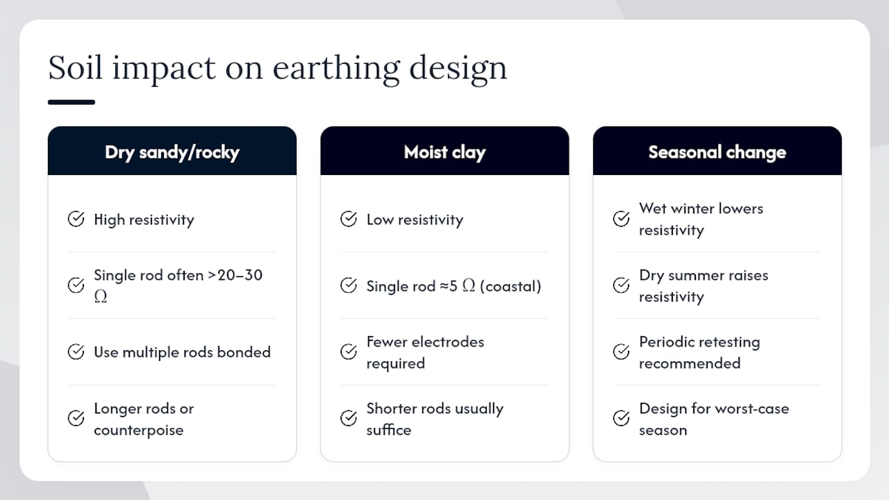
Soil resistivity determines how easily current disperses into the ground, and it varies enormously by soil type. Sandy, dry soil resists current flow and often demands longer electrodes, more rods, or chemically treated ground enhancement to hit a usable resistance figure. Clay-heavy or consistently moist soil conducts far more readily and typically needs less electrode work to reach the same target.
This is why a one-size electrode design fails so often. An installer who drives a single standard rod on a coastal property with damp clay might comfortably clear 5 ohms. The same single rod on dry, rocky, or sandy ground inland can sit stubbornly above 20 or 30 ohms no matter how deep it goes.
Practical responses to poor soil conditions include driving multiple rods spaced apart and bonded together, using longer rods to reach moister subsoil layers, or laying horizontal counterpoise conductors where rock prevents deep driving. Seasonal variation matters too. Soil that reads well in a wet winter can test considerably worse in a dry summer, which is part of why periodic retesting isn't just bureaucratic box-ticking, it catches drift that a one-time commissioning test would never reveal.
Before finalizing an electrode design, a quick resistivity check on-site, even an informal one, tells you far more than assuming a standard rod configuration will work everywhere.
Safety considerations and risk mitigation for improper earthing
An improperly earthed inverter isn't just a compliance problem, it's a shock and fire hazard sitting on the roof. Without a proper equipment grounding path, a fault in the array or inverter can energize metal frames, rails, or the inverter chassis itself, turning ordinary contact into a shock risk for anyone touching the system, including firefighters responding to an unrelated blaze.
Fault current with nowhere safe to go tends to find the next-easiest path, sometimes through building wiring, sometimes arcing at a loose connection. Arc faults at poorly bonded joints are a genuine fire risk, and they're notoriously hard to spot visually since the damage often happens inside a joint that looks fine from outside.
Risk mitigation here isn't complicated, it's disciplined. Test every bond before covering it up. Never assume continuity where you haven't measured it. Treat isolation-monitor alarms on the inverter as a real fault signal, not a nuisance trip to silence. And where a system has been running for years without ever being retested, treat that as an open question rather than an assumption of safety, particularly if the property has seen any lightning activity, roof work, or renovation since the original installation.
How moisture, temperature, and corrosion affect earthing over time
An earthing system that tests perfectly at commissioning doesn't necessarily stay that way. Moisture in soil actually improves conductivity in the short term, which is why resistance readings often look better right after rain, but that same moisture accelerates corrosion at buried clamps and splices over years, quietly raising resistance at the exact points you can't see without digging.
Temperature swings affect soil resistivity too, dry, frozen, or baked ground all conduct less effectively than moderately moist soil at moderate temperature. This is part of why a single earth resistance reading taken on a good day doesn't guarantee performance year round.
Corrosion is the slower, more insidious threat. Galvanic corrosion between dissimilar metals, aluminium against copper, mild steel against a stainless clamp, degrades a connection from the inside, and by the time it shows up as a rising resistance reading, physical damage has often already occurred at the joint. Coastal properties see this fastest, salt air accelerates corrosion rates dramatically compared to inland sites.
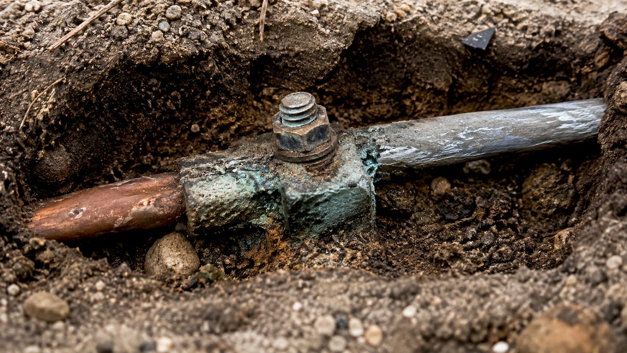
The fix isn't complicated: match materials correctly, use corrosion-resistant hardware where budget allows it, and retest periodically rather than trusting a commissioning result to hold indefinitely. A resistance reading from three years ago tells you very little about a connection sitting in salt-laden coastal air today.
How Solarza connects you with installers who get earthing right
Getting earthing right depends entirely on the installer doing the work, and that's precisely where Solarza's vetting process earns its keep. Every installer in Solarza's network is verified and rated by homeowners across all nine provinces, which means you're not gambling on whether the person on your roof actually understands the difference between a transformerless inverter's isolation monitoring and a transformer-isolated unit's bonding requirements.
Before hiring anyone, ask directly: how many CoC-compliant installations have you signed off under SANS 10142-1, and what's your process for verifying rail continuity before commissioning? A confident, specific answer tells you more than any brochure. Solarza's solar calculator and installer comparison tools help you shortlist candidates who've already built that track record, rather than starting from a blank search.
— Kobus Kohvik
Get matched with a compliant installer through Solarza
Solarza is the direct route to a vetted installer who won't cut corners on earthing, no cold-calling contractors or guessing which company actually knows the difference between functional and protective grounding. You tell us your location and system needs, and we match you with verified, rated installers who've already done this work correctly across your province.
The process is simple: request a free quote and get matched with installers who can walk you through their commissioning process before you sign anything. Compare candidates by city or by the specific services they offer, check their ratings, and ask each one directly about their CoC track record and earth resistance testing practices. Always verify an installer's credentials and registration status yourself before committing, Solarza's vetting narrows the field, but the final conversation is yours to have.
Standards and guides worth keeping on hand
The earthing requirements covered here draw primarily on SANS 10142-1, the governing standard for wiring and bonding in South African electrical installations, alongside inverter manufacturer manuals that specify topology-specific grounding rules and SPD manufacturer guidance on correct placement and bonding. Solarza's inverter and residential installation guides offer further detail on equipment selection.
Always check the exact wiring diagram for your specific inverter model rather than relying on general rules alone, manufacturers occasionally deviate from typical topology behavior, and that deviation is exactly where inspection failures happen.
Sources
- Solar PV safety standards (SANS 10142) guidance
- Transformerless inverter grounding: never add a DC ground
FAQ
Should a solar inverter be grounded?
Yes, the inverter chassis and every exposed metal component must be equipment grounded for safety under SANS 10142-1. Whether a DC conductor also gets intentionally earthed depends on whether the inverter is transformerless or transformer-isolated.
How do I earth a solar inverter?
Bond the inverter chassis, module frames, rails, and metal conduit using listed bonding hardware and continuous copper conductors, then connect the whole system to an earth electrode sized to the OCPD rating. A registered electrician tests continuity and earth resistance before signing the CoC.
Does an inverter need earthing?
Every inverter needs its chassis and enclosure earthed for protective purposes, that part is never optional. Additional DC-side functional grounding depends entirely on the inverter's topology and the manufacturer's specific wiring instructions.
What happens if an inverter is not grounded?
An ungrounded inverter creates a serious shock and fire risk, since fault current has no safe path back to source and can energize metal frames or the chassis itself. It will also fail CoC inspection, which puts insurance claims and manufacturer warranties at risk if anything goes wrong later.